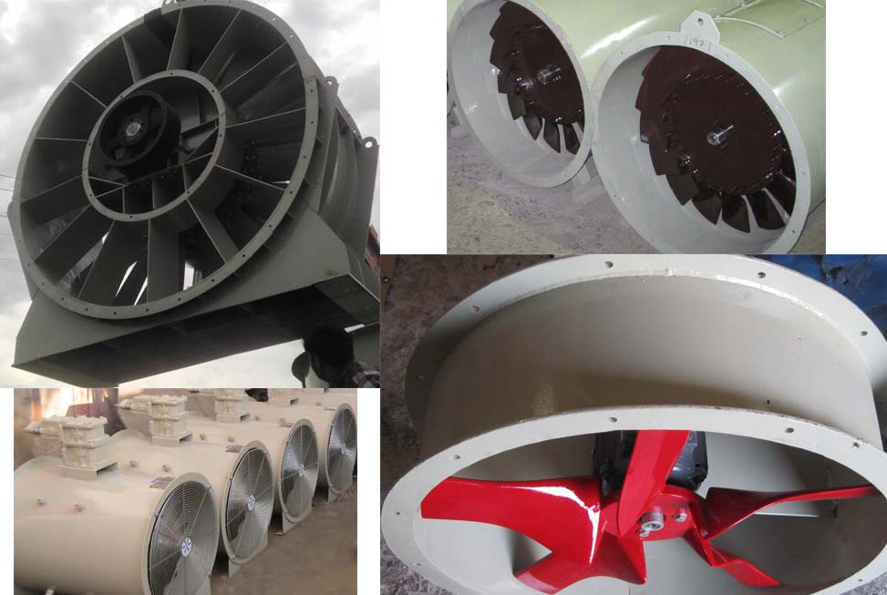
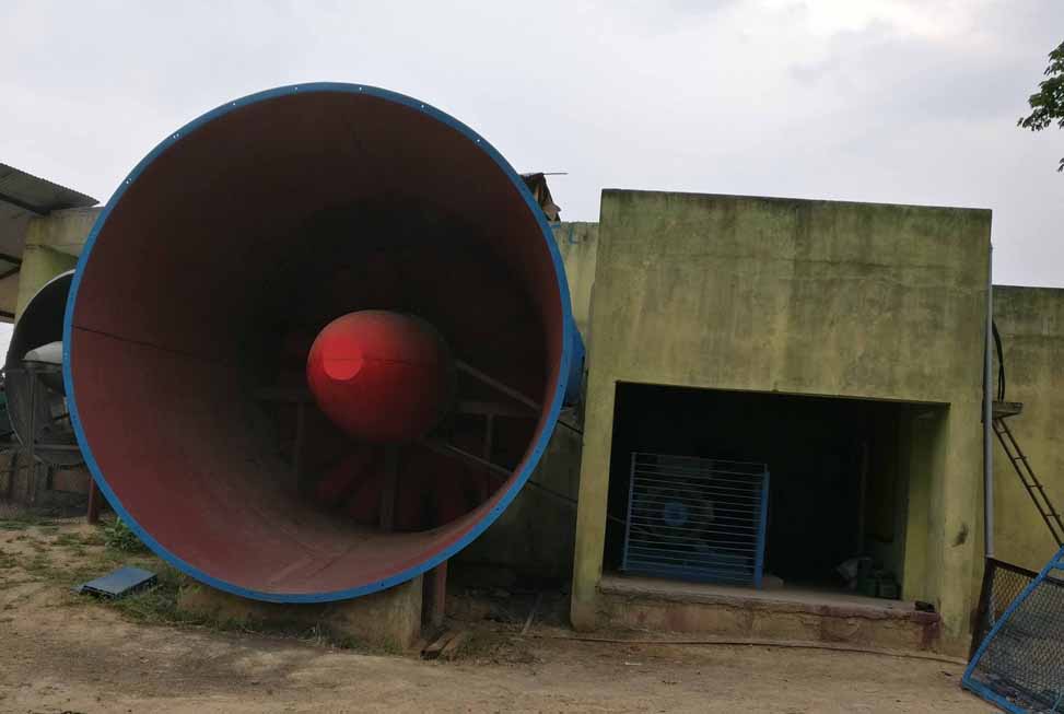
FRP Fan stack is also known as Fan ring, Fan Cylinder and Fan Shroud
What is fan stack or fan ring
Fan stack is a boundary around the fan to separate air inlet and air delivery. It has three main components fan cylinder or fans cashing, air inlet or inlet bell, and fan diffuser or velocity recovery cone.
Fan stacks used for the following function
- It maximizes fan efficiency.
- It reduces sound levels near the fan system.
- Stack prevents the reverse running of the fan due to external air interference.
- The Inlet bell provides smooth airflow to the fan.
- The Inlet bell also restricts vena contracta at the fan inlet.
- Fan stack also minimizes discharge air recirculation.
We are a manufacturer of FRP fan stack. Our fan stacks have designed for the smooth surface finish on the working part as well as having superior strength.
In some fan systems, individual components of the stack used alone or with each other.
Fan Stack component

Fan Cashing
it is the portion where fan operate it has to be there in all case.

Air Inlet
It used to ease smooth air entry to the fan.

velocity recovery
Stack Diamater Range Up To
Stack Height range up to
Maya Fan Stack Kay feature
- Our Fan stack enables high velocity-recovery efficiency. Which improves system efficiency and reduced operation cost.
- Fan stacks manufactured from high-quality fibreglass-reinforced plastic.
- Maya fan stack is of double-finish design.
- The smooth inner surface of fan stack drops friction losses. Which provide laminar airflow and reduce turbulence.
- outer surface provides high resistance against climatic conditions.
- High-quality UV protection on both the surface prevents UV rays hamper the stack life.
- Fiber fan stack is reliable yet less in weight. This contributes to improving the cooling tower life.
In some case Fan stack of an extended height required, to promote the discharge of the saturated airstream at higher elevations. It minimizes the effects of recirculation and interference.
The cooling tower fan stack is also known as a cooling tower fan shroud and cooling tower fan cylinder.
Fan Stack is an essential part of the system manufactured from fibre-reinforced plastic (FRP).
Fan Stack is a common term in cooling tower industries for the combination of three components of airflow path it includes-
- An air inlet is also known as fan bell or bell inlet.
- Fan casing the part in which fan operate this is also known as fan cylinder, fan shroud and fan ring.
- The third part of the stack is a velocity recovery cone. It used to recover velocity pressure with the help of a conical divergent at fan exit this also known as fan diffuser.
These stacks have vertical and horizontal ribs which make it very strong to sustain in high wind velocity conditions. We have the in-house capability to develop pattern and mould, so we make any size of fan stacks, and it manufactured in assembled segments.
Fan Air Inlet/ Inlet bell / Fan Bell
In the fan system, the air behind fan come from large volume and have to pass through a small cross-section of the fan casing.
So fan develops negative pressure behind the fan, this pressure is equal in all direction, so it sucks air from every direction.
This air moves toward the fan radially on the smallest distance path. Thus, some of the air move perpendicular to the axis of the fan.
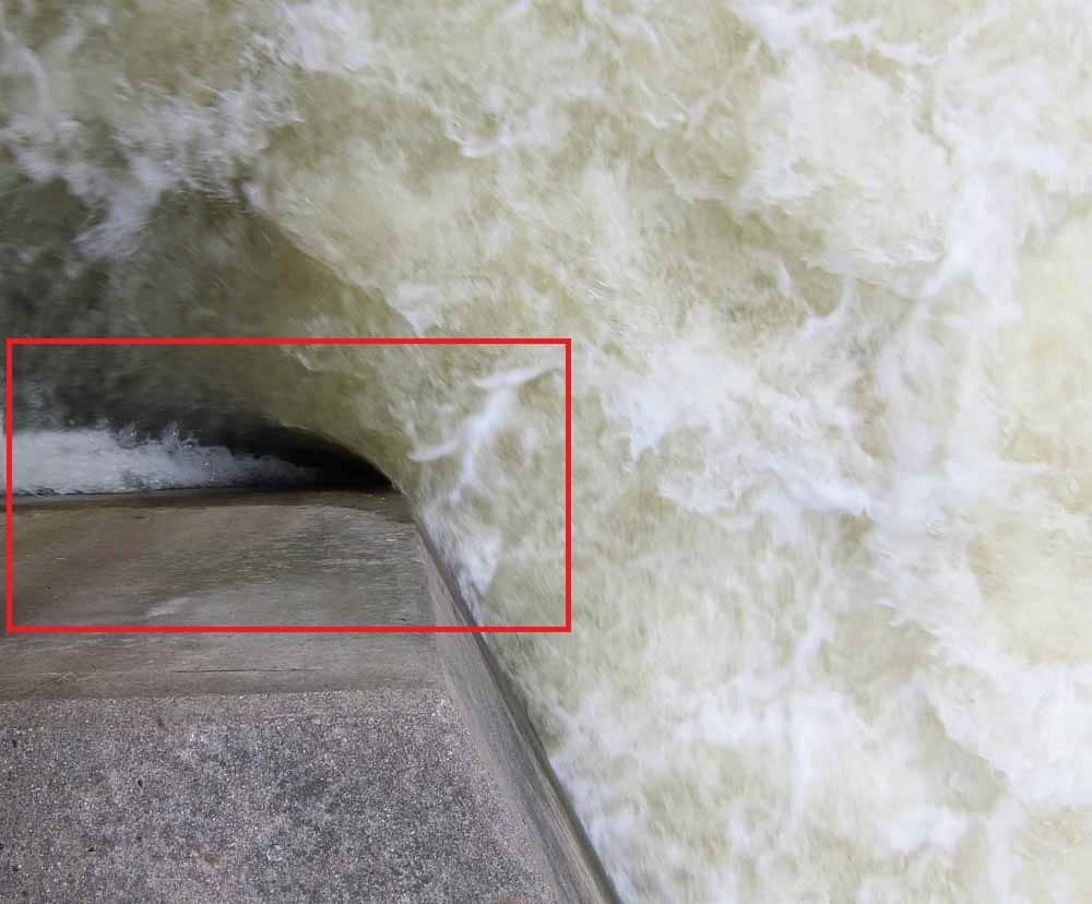
Due to inertia of air coming other than axial direction so resultant air bend toward the centre of cashing and create Vena contracta.
It is like the picture at right having visible vena contracta at a canal.
These phenomena remain much more severe in fans as the velocity of air in fan is much higher, thus it impacts the fan performance.
So to ease the smooth transition of air at fan inlet different shapes utilized to reduce the losses these known as Fan air inlet, inlet bell or fan bell.
This inlet bell provides:-
- Uniform flow at inlet.
- Lower fan noise.
- Reduce Turbulence.
- Reduce pressure drop and horsepower
- And increase airflow at the same fan power.
Types of fan air inlet
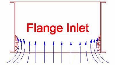
FLANGE INLET
Most of the time casing with flange and in some cases an extended piece provided to allow some extra distance for air equalization.
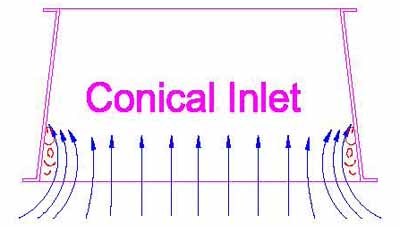
CONICAL INLET
A conical shape added which increase effective inlet area but the disadvantage of flange inlet still exist
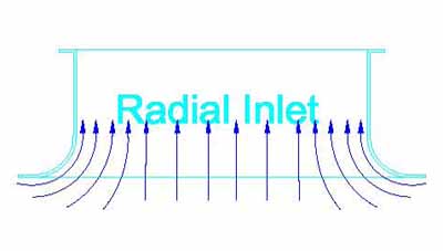
RADIAL BELL
It is a most used inlet type and having a very good advantage on system.
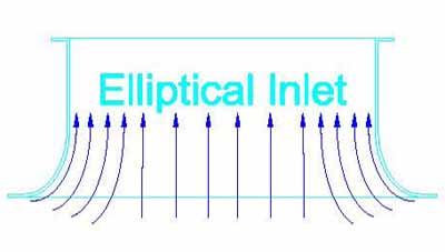
ELLIPTICAL BELL
It used in cooling tower and mining industries have a very good effect of flow guiding and equalization.
Partner of India’s Largest ACC fan ring supply
At a project of National thermal power corporation (NTPC) which is India’s largest power producer. This handled by the Bharat Heavy Electrical Ltd (BHEL) one of the government giant for EPC project. And ACC of the project supplied by Harbin Air conditioning (HAC)
- The first time NTPC is using ACC for the power plant.
- It is India’s Largest ACC and maybe Asia’s Largest.
- The project having 3 unit of 90 cells.
- Fan size is 36 foot.
Not only supply fan ring, but we also supplied the fan guard for the project.
Fan ring and Guard
Single Projects Supply
Fan casing
It is the boundary which shrouded around the fan and cylindrical in shape, so, it is also known as fan cylinder or fan ring.
It is the most important part which partition +iv and –iv pressure plain.
Back of fan is suction side it is –iv pressure plane of fan and front or delivery side is +iv pressure plain.
The casing should be as accurate in shape as possible because in case of any irregularity it can cause vibration and may develop fatigue on the fan blade.
It is very important to maintain least tip clearance which is a space between the blade tip and casing, as this is the place where two different pressure plane come in contact thus air tends to move back from +iv pressure to –iv pressure side.
So it is always preferable to maintain the smallest and uniform tip clearance and It should be less then 1% of diameter.
Also, the problem of tip clearance become more critical with increasing static pressure in the fan.
With increasing tip clearance efficiency of a low-pressure fan spoiled up to 20 % and high-pressure fan will get stalled and the air starts circulation from this space.
We provide:-
- Heavy-duty robust integrated casing for mining fans.
- FRP cashing for OEM of cooling tower and ACC.
- Fan shroud/ring in combination with inlet bell, delivery diffuser or both.
FAN DIFFUSER / VELOCITY RECOVERY CONE
In a general significant amount of effort made by the fan wasted in exit air energy. A fan draws air from the system and delivers it to the environment at atmospheric pressure (At zero pressure). So velocity recovery cone which is a conical cylinder of increasing diameter is an ideal tool to cut this exit air velocity. This utilised the largest amount of dynamic pressure recovery into the static pressure regain. The energy of air at any point of the system remains the same. Thus energy at fan and energy at exit is same only some loses in the path from fan plane to the exit plane happened so it can derive as –
Psf + Pvf = Pse+Pve+ L
Psf = Pve – Pvf + L
Psf = Static pressure at fan
Pvf = Velocity or dynamic pressure at fan
Static pressure at diffuser exit is zero. (Atmospheric pressure) Psf = Velocity pressure at diffuser exit L = losses (common rule of thumb is 70% of the difference in velocity pressure (Pve – Pvf) recovered in recovery cone portion of the cylinders. In actuality, this percentage may vary from 50% to 95%. Depending on fan operating conditions and fan diffuser quality i.e. shape consistency and finish of inner surface) Since the velocity of discharge air stream reduces at the exit of fan diffuser. Pve is less than Pvf. This means that relative to atmospheric pressure, static pressure at a point just above the fan plain becomes more negative by adding recovery cone.
So by adding velocity recovery cone pressure against which fan operates reduced compared to no use of velocity recovery cone.
This is a significant advantage and improved fan system performance to a great extent. So with the use of velocity recovery cone, the same air can deliver at much lesser power consumption. Or with the same power, a higher quantity of air can deliver.
A diffuser is converting dynamic energy into static pressure. Thus higher the exit air velocity, a greater advantage of velocity recovery cone can be achieved. In a different application of fan velocity recovery cone used are different. It depends on installation conduction and exit air quality. Like in the cooling tower it remains part of fan stack and constructed in combination of casing and air inlet. Also as this diffuser have to deal with the humid air thus mostly it constructed with the material like wood, concrete and FRP. In cooling tower long fan diffuser also help is the prevention of plum recirculation by delivering it at a higher elevation. In mine ventilation fan diffuser is mostly made of steel and very long as it Handles high-speed air and having high dynamic pressure.
FEW OF OUR PRESTIGIOUS CUSTOMER


Few important calculations of “Fan Stacks”
Pressure Recovery By Fan diffuser :
Effect of inlet shape on Dynamic Pressure

